Adam Stork, James Middlemass, and John Long
Ergonomics & HCI Unit, University College London
26 Bedford Way London WC1H OAP
ABSTRACT
MUSE, a structured Method for Usability Engineering, was created to improve the practice of Human-Computer Interaction practitioners, a practice that is primarily one of designing artefacts that fulfil user requirements. This paper offers a case-study application of MUSE to a set of domestic energy management user requirements to produce an artefact. The paper presents: an overview of MUSE; the necessary features of an application; the user requirements; the details of the application; the resulting artefact; and an assessment of the artefact with respect to the user requirements. Finally, it is argued that this case-study be considered ‘successful’, where a successful case-study extends the known frontiers of application of MUSE.
Keywords
Human-Computer Interaction; Human Factors; Structured Methods; Energy Management Systems; Planning and Control; Software Engineering
1. Introduction
The current practice of Human-Computer Interaction (HCI) is primarily one of designing artefacts that fulfil user requirements. MUSE, a structured Method for Usability Engineering (Lim et al., 1992 for an overview; and Lim & Long, 1994 for detail), was created to improve the practice of HCI practitioners, i.e. their ability to design artefacts that fulfil user requirements. MUSE was developed using a strategy for structured (human-factors) method development (Lim et. al, 1990) which involved (in the main) iterative proposition of a version of the method followed by testing through its application to the design of some interaction artefact. These applications are termed case-studies. Successful case-studies, those which produce interaction artefacts fulfilling the user requirements, extend the known frontiers of application of the method; while unsuccessful case-studies delimit the frontiers and provide input to the development of further versions of the method. To be testable, the known frontiers of application of the method can be expressed in terms of how well-defined, complex, and observable are the user requirements of successful and unsuccessful case-studies.
MUSE has been fully documented in the HCI literature (Lim et al., 1991; Lim & Long, 1992). These references include reports of the application of MUSE. However, these case-studies have primarily exposed and exemplified the method. In contrast, the focus here is on the successful or unsuccessful aspects of a case-study as defined above. Thus, this paper reports a successful case-study of MUSE: an application that produced an artefact which is claimed to fulfil a set of user requirements.
The user requirements for the case-study resulted from an observed problem with the energy management of a specific home under study, the home of A and S. These user requirements arose in the context of other research (Stork & Long, 1994) which required them to be well-defined and relatively simple. These requirements make it possible to report the case-study in a paper of this length. The clear definition and simplicity, however, do not detract from the consequences for MUSE of a successful case-study, since its frontiers of application still become better known . Further, these consequences could be extended, since the user requirements can be claimed to have similarities with less well-defined and more complex, but equally observable, user requirements. The claim that this case-study is successful is based on a demonstration that: the resulting artefact fulfils the user requirements; and that MUSE was applied in the development of that artefact from the user requirements.
The paper describes: an overview of MUSE; the necessary features of a MUSE application; the case-study’s user requirements; an appropriately detailed (to highlight those features) application of MUSE to the user requirements to produce an artefact; the resulting artefact; and an assessment of whether the artefact fulfils the user requirements. Finally, some conclusions are suggested and further research is identified.
2. Overview of MUSE
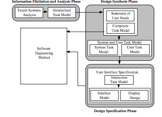
MUSE is a structured analysis and design method for use by human factors engineers. The method aims to improve the practice of HCI practitioners by providing support for the integration of human factors with existing structured methods for software engineering, such as Yourdon, JSD, or SSADM. The output of MUSE is the specification of an interaction artefact, the software engineering method producing the specification of an implementable artefact, incorporating the interaction artefact.
MUSE supports design in a ‘top-down’ manner based on information derived ‘bottom-up’ and progresses from the specification of general features of the tasks to be performed by the user, derived from analysis of the user requirements and from existing systems, to the specification of the details of the interaction artefact. The application of MUSE is an iterative process, both overall and internally, supporting the production of the best first-attempt artefact, following the initial complete application.
Figure 1 shows a schematic diagram of MUSE with an unspecified software engineering method. MUSE has three phases: the Information Elicitation and Analysis phase; the Design Synthesis phase; and the Design Specification phase. The Information Elicitation and Analysis phase supports primarily: the assessment and re-use of components of extant systems; and the maintenance of the consistency of the design with the user requirements. The Design Synthesis phase supports primarily: the conceptual design of the interaction artefact; and the maintenance of the consistency of the design with the semantics of the domain and a human factors interpretation of the user requirements with respect to the analysis of extant systems. The Design Specification phase supports primarily: the detailed design of the interaction artefact. Mandatory checking and exchange of information with the software engineering method occurs to ensure that the interaction artefact is implementable and to support overall design agreement and consistency.
3. Features of a MUSE Application
MUSE, in order to improve the ability of HCI practitioners to design artefacts that fulfil user requirements, is concerned to ensure that (the features are labelled to permit later reference):
a. the artefact is considered completely and appropriately at all levels of design, from conceptual to detailed;
b. the artefact is consistent across all levels of design (including the user requirements);
c. domain knowledge is assessed and applied to the artefact at appropriate levels of design;
d. human factors knowledge (as well as software engineering knowledge) is assessed and can be applied to the artefact at appropriate levels of design;
e. desirable qualities of extant systems are assessed and can be integrated into the artefact at appropriate levels of design;
f. the design rationale contained in the previous three concerns can be made explicit with respect to the artefact;
g. MUSE achieves these concerns, in part, by stipulating the generation of products. An application should, therefore: contain the specified explicit products that have the scope defined by MUSE; are in the notation defined; and have been produced, using the processes defined. If any product is not relevant, a suitable statement should explain why it is not relevant.
In addition to the products, evidence of the above concerns should be available in an application of MUSE, for example: that suitable human factors knowledge concerning the allocation of function between the user and the device has been applied.
4. The User Requirements
Other HCI research, reported elsewhere (Stork & Long, 1994), required the study of an energy management problem in a home. This problem had to be observed (and observable), well-defined, and relatively simple. Because it fulfilled these criteria, the following energy management problem in the home of A and S was selected from a list of such problems compiled by the occupants:
“The domestic routine of A occasionally requires him to remain at home to work in the mornings, rather than to leave earlier with his partner, S, to work at his office. However, if A leaves after 8 o’clock in the morning, or stays at home to work, then the house is too cold until he turns the gas-powered central heating back on. If he expects to be at home for a short time after 8 o’clock, then he often uses the one-hour boost facility on the heating controller to turn the heating back on, which can result in him being too cold, if he is at home for longer than expected. A’s ability to work is adversely affected by being cold and having to control the heating. A finds it difficult to plan much in advance, either whether he is staying home to work or, if he stays, how long he will stay to work. The current gas bill is acceptable and an increase could be tolerated, although a decrease would be desirable.”
The user requirements for this application of MUSE were for a bespoke artefact to solve the above problem at a reasonable cost for the envisaged benefits. The user was expected to be A and he was not prepared to spend much time using or learning to use the new artefact.
4. The Application of MUSE to the User Requirements
The features of a MUSE application are highlighted in this section by reference to their associated label (superscripted at the end of the sentence containing the feature).
4.1 Information Elicitation and Analysis Phase
A list of extant systems that could be assessed (Figure 1—Extant Systems Analysis) was constructed: the existing system; related systems with tasks in common, such as other home energy management systems (for example, home heating control systems); partially related systems, such as home management systems (for example, support for planning food purchases), energy management systems (for example, office heating systems), and general management systems (for example, decision support or security systems)e. It was decided only to analyse the existing system for the first iteration of the application of MUSE. It was considered that this analysis would lead to a better understanding of the user requirements, would offer most potential for re-use to the design, and might suffice (b,e).
Human factors techniques were used to analyse the existing system in two ways: a task analysis was conducted on the basis of an interview in which A introspected about his days; and A was asked to keep a diary for several mornings during which he stayed at home and left for workd. These analyses were expressed in ‘structured diagram’ form with accompanying tables as MUSE ‘Task Description’ productsg. An extract from the highest level of the Task Description of the first and second days of the diary are shown in Figure 2 (the outlined boxes indicate that there is more detail below these nodes in the complete diagram). The diagram for the first day shows that A performed some early morning tasks and stayed to work; and the diagram for the second day shows that A performed some morning tasks again, but left with S.
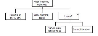
To gain an understanding of ‘generic’ mornings (which the design needs to support), a generic Task Description across all days was produced from the diary Task Descriptions of each day (b,g). Figure 3 shows an extract from the highest level of this description and Figure 4 shows an extract from the accompanying table. The table demonstrates that implications and speculations concerning the design were considered and explicitly documented throughout this stage of MUSE application (b, c,d,e,f).
| Name | Description | Observation | Design Implication | Speculation | |
| Most weekday mornings | This is a generalisation of three weekday mornings | These appear to represent the three different types of workday mornings that A has. | The other days should not be affected as they are not part of the problem. | Retain the existing system to some extent.Useful to assess other days for confirmation and other options. | |
| Leave? (before heating off) | Generalisation of the activities that can occur before the heating goes off: work or leave. | A appears to plan using some information sources: a diary and a to-do list. These are stored electronically. | Perhaps interface with the diary/to-do list (but diary/to-do-list plan does not predict reality very well)?Adaptive/predictive controller: Probably not because 1) does not seem to be a predictable task 2) technology not very advanced. |
Figure 4. An extract from the table of the generic Task Description of the diary analysis of the extant system .
The generic Task Descriptions produced using the diary and the task analysis (based on introspection) were combined into a structured diagram with an accompanying table as a MUSE ‘Generalised Task Model of the extant system’ product (Figure 1) (b,g). An extract from the highest level of the Generalised Task Model of the extant system is shown in Figure 5.
Figure 5. An extract from the structured diagram of the Generalised Task Model of the extent system.
At this point, it was decided that sufficient analysis of the extant system had been performed to consider the initial design of the target artefacte. A task-level conceptual design was constructed based on: the user requirements; and the design implications and speculations produced by the analysis of the extant system (a,b,e). This design was documented in a structured diagram and table as a MUSE ‘Generalised Task Model of the target system’ productg. Figure 6 shows an extract from the highest level of the Generalised Task Model of the target system, and Figure 7 an extract from the accompanying table (Figure 1). The extracts demonstrate that the design is consistent with the user requirements and that it arises from the understanding gained through the analysis of the extant systemb,e. The table identifies a human factors concern that the user must remember to turn the heating off and that this requirement has yet to be addressed (a,d,f).
Figure 6. The structured diagram of the Generalised Task Model of the Target System.
| Name | Description | Design Rationale |
| Leave? | Allowing for planning and control of staying at home and working or not. The iteration is to cater for the period of re-planning and controlling. On leaving, or just before, the heating must be turned off. A quit construct (for the diagram) must be included in this body to allow for the leaving, otherwise A is assumed to stay (end of the diagram at the end of the morning). | Discomfort due to cold avoided by having no cold. Risk of not turning system off must be addressed within this design. |
Figure 7. An extract from the table of the Generalised Task Model of the target system.
The initial high-level design, when compared with the high level extant system analysis, suggested a potential for re-use of more detailed extant system features and it was decided to perform a more detailed analysis of the extant system to support that potentiala,e. Accordingly, a range of MUSE products was developed that analysed the extant system from its conceptual to its detailed designg. This range of products was complementary to the range of MUSE products to be produced later during design synthesis. This paper will only show examples of these products to highlight the level of analysis of concern; the recording of design implications and speculations at that level of concern; and to facilitate later examples during the synthesis phase (as required by the features of MUSE application—see earlier) (e,f).
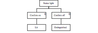
The tasks recorded in the Generalised Task Model that were directly supported by the existing controller (the on-line tasks) were analysed in further detail to produce a structured diagram and table for the MUSE ‘System Task Model of the extant system’ product (e,f,g). Figure 8 shows the complete structured diagram and Figure 9 an extract from the table. The table entry provides an example of the documentation of an assessment for re-use of a human factors guideline and its application to the extant system (d,e,f).
Figure 8. The structured diagram of the System Task Model of the extant system.
| Name | Description | Design Speculation |
| Confirm off | Heating system confirms that the heating has been turned off. | Immediate feedback should be retained in target system. |
Figure 9. An extract from the table of the System Task Model of the extant system.
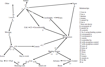
Further MUSE analysis products were developed that: determined the semantics of the domain of the extant system; assessed the impact on the content, format, and mode of presentation of the extant design from off-line tasks (those not supported by the extant controller); and considered a detailed analysis of the extant system (e). The detailed analysis considered the relationships between the specific behaviours of the user of the extant controller and the tasks of the system; the specific behaviours of the interactive device and the tasks of the system; and the layout and content of the appearance of the extant systeme. Some of these products are exemplified here: the semantics of the domain were captured by interview and observation in a semantic net diagram and a table in a MUSE ‘Domain of Design Discourse of the extant system’ product (Figure 10); the relationships between the specific behaviours of the interactive device and the tasks of the system were shown in a structured diagram and table in a MUSE ‘Interaction Model of the extant system’ product (extracts in Figures 11 and 12); and the layout of the appearance of the extant system were shown in a layout diagram as a MUSE ‘Pictorial Screen Layout of the extant system’ (Figure 13) (d,e,g).
| Name | Description | Design Speculation |
| Status light | A light that can be illuminated or extinguished. When lit, it shows that the heating is on; when extinguished, that it is not. | The same style of light could be retained as it has shown to be effective for showing the status. |
Figure 12. An extract from the table of the Interface Model of the extant system.
Figure 13. The Pictorial Screen Layout of the extant system.
To ensure consistency with the user requirements and the early assessment of human factors issues a textual summary of the human factors’ concerns was constructed, based on the user requirements and the analysis of the extant system, as a MUSE ‘Statement of User Needs’ product (Figure 1) (b,d,g). This statement detailed: any explicit design criteria, such as the artefact cost should be acceptable for the benefits; any implicit design criteria, such as the functionality of the existing controller should be retained to support non-weekday-morning tasks; any explicit system performance criteria, such as A must not be cold; any implicit performance criteria, such as A must be permitted to leave home when he desires (constraining should not be considered a solution); and any relevant human factors knowledge, such as an extension of a guideline by Shneiderman (1992) that “human action should be eliminated where no [human] judgement is required” to include “and minimise human action where human judgement is required” (b,c,d,e,g). This extended guideline confirmed the high-level design expressed in the Generalised Task Model of the target system.
The semantics of the domain were considered and determined to be the same as the semantics of the domain of the extant system (a). The Domain of Design Discourse of the extant system MUSE product developed during the extant system analysis was re-used as the MUSE ‘Domain of Design Discourse of the target system’ product (e,g). The product emphasises the importance of the temperature of the house and its relationship with the comfort and location plan of A (c). The explicit existence of this domain knowledge enabled it to influence the final artefact (c).
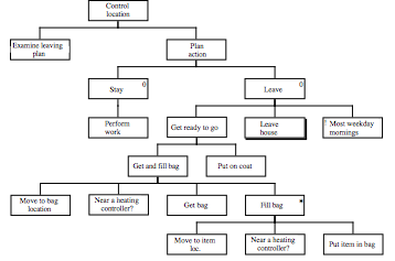
The conceptual design of the conjoint user and computer tasks was advanced, maintaining consistency with the accepted foundation of the Generalised Task Model of the target system, and was expressed in a structured diagram and table as the MUSE ‘Composite Task Model’ product (Figure 1 and extracts in Figure 14 and 15) (a,b,g). Important design decisions were rationalised at this stage: the provision of a controller in the same location as the existing one; and the further provision of a controller near the front door (partially shown in the extracts which show some of the continuation of the design from the Generalised Task Model of the target system) (c,d,e,f).
There was significant re-use of extant systems analysis at this stage with modifications to support the designe. For example, the decomposition of the ‘control location’ task was re-used from the generic Task Description of the extant system and modified to remove extant heating control tasks if A stays, and to add new heating control tasks on A leaving. These additions were consistent with the user requirements and the guidelines in the Statement of User Needs (b). A human factors concern was raised over the need for reminders, in addition to the locations of the controllers, to ensure that A turns off the heating (d).
| Name | Description | Design Rationale |
| Get and fill bag | If A is near either heating controller while collecting his bag or filling his bag then he should use it to turn off the heating. | The bag collection and filling always happen 5-15 minutes before leaving. The plan is sufficiently formed to ensure that leaving is inevitable. It is cost effective to turn the heating system off before leaving, as long as it is not turned off forty minutes before leaving, as this affects comfort.The location of the front door controller (near the base of the stairs) and the main controller is near the location that the bag and some contents are often kept. |
| Near a heating controller? | Either of the two controllers, the kitchen (main) controller and the front door controller, should remind A to turn the heating off and allow him to do so. This design will require a new front door controller and an enhanced main controller that can be programmed differently for the weekends as from the weekdays. | To upgrade to a new, slightly more sophisticated, main controller will not cost very much (approx. £30). The front-door controller can be built cheaply (£10). This will transfer the ability to use the existing controller; maintain the functionality for the other days; and provide the desired level of comfort. The risk is that the heating is left on: the location beside the front door will try to prevent this, but a further reminder should be built into the controllers. |
Figure 15. An extract from the table of the Composite Task Model of the target system.
The on-line tasks (to be supported by the artefact) and off-line tasks (un-supported by the artefact) were identifieda. Further decomposition of the off-line tasks ensured that there were no content, format, or mode of presentation issues for the target system (a). (It was possible to re-use the off-line task descriptions from the extant system analysis of tasks (e)).
The design was considered at a lower level of detail by the decomposition of the on-line tasks, documented in a structured diagram and table as a MUSE ‘System Task Model’ product (Figure 1 and Figures 16 and 17) (a,g). The on-line tasks description diagram shows that they are similar to the analysis of the extant system (e). This similarity is rationalised in the table (shown) as consistent with the human factors guidelines of ‘transfer of learning’, ‘feedback’ (which the extant system achieved as shown earlier), and ‘consistency’ (Smith & Mosier, 1986) (d,e,f).
The final consideration at this level of detail was the allocation of function between the user and the artefacta. In this case, it was considered difficult, if not impossible, to allocate the user’s leaving plan to the controller, so it was decided that the controller should simply respond to the user’s control commandsd. This allocation corresponds with the human factors guideline that humans are generally better than computers at “drawing on experience and adapting decisions to situations” (Shneiderman, 1992) (c).
Figure 16. The structured diagram of the System Task Model of the target system.
| Name | Description | Design Rationale |
| Advance (off) | The advance facility should be used to control the heating. | Use of the advance facility to turn the heating off transfers the understood behaviour of the existing system. Advance (off) behaviour ported from extant system. |
| Confirm on | Confirmation that heating is on. | Feedback on commands ported from extant current system. Consistency maintained for remind to turn off. |
Figure 17. An extract from the table of the System Task Model.
4.3 Design Specification Phase
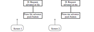
The design of the relationships between the behaviours of the user and those of the designed controllers was documented in a structured diagram and table as a MUSE ‘Interaction Task Model’ product (Figure 1 and Figures 18 and 19) (a,g). The design is consistent with the System Task Model product, as it represented a decomposition of the user (designated ‘H’—human) input required to perform the task (b). The extract from the table documents the rationale behind re-using an advance push button to turn off the heating (e,f). Application of the human factors guideline ensures that ‘consistency’ is maintained between the two controllers (d).
Figure 18. The structured diagram of the Interaction Task Model of the target system.
| Name | Description | Design Rationale |
| Press fdc advance push button | A press of the fdc advance button (if the heating is on) will turn the heating off. | Extant current system has an advance button on the main controller: use ported to front door controller in target system. |
| Press mc advance push button | A press of the mc advance button (if the heating is on) will turn the heating off. | Extant current system has an advance button on the main controller: use ported to new main controller. |
Figure 19. An extract from the table of the Interaction Task Model of the target system.
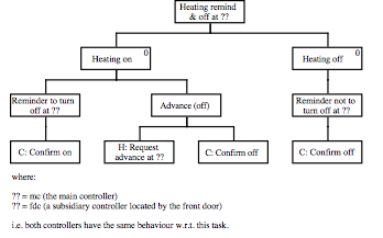
The corresponding design of the behaviours of the designed controllers was documented in a structured diagram and table as a MUSE ‘Interface Model’ product (Figure 1 and extracts in Figures 20 and 21) (a,g). The design is consistent with the System Task Model product and the Interaction Task Model product in that it represents a decomposition of the device (designated ‘C’—computer) output required to perform the task (b). The design also re-uses behaviour of the extant system, for example: a light (shown earlier) and an advance push button (shown in extract) are specified to support the same tasks, of confirming the change of status and changing the state of the heating, as they support in the extant system (e).
| Name | Description | Design Rationale |
| Advance push button at ?? | A push button on the front door controller and the main controller. | The behaviour for this button is ported from the extant current system. Consistency of behaviour between controllers. |
Figure 21. An extract from the table of the Interface Model of the target system.
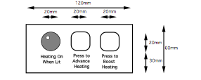
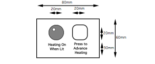
The control panel layouts were specified and documented in a MUSE ‘Pictorial Screen Layout’ product (Figure 1—Display Design) (a,g). Since the behaviour of the main controller is the same as the behaviour of the existing controller and the layout of the existing controller is considered satisfactory, the layout of the existing controller was re-used from the analysis of the extant systeme. The front door controller layout was dimensioned to allow suitable access to the controls (extract in Figure 22) (c). The layouts’ objects were specified in a MUSE ‘Dictionary of Screen Objects’ product (Figure 1—Display Design—and extract in Figure 23) (a,b,g).
Figure 22. An extract from the Pictorial Screen Layouts (the front door controller layout).
| Screen object | Description | Design attributes |
| Push button for fdc advance (Maplin QCA9202403 or equivalent). | A tip-of-finger-sized button that can be depressed and springs back to its previous position. Advances the state of the heating at the front door controller. | A push toggles the current state of something. Advances the state of the heating. |
Figure 23. An extract from the Dictionary of Screen Objects.
Two MUSE products were not considered to be relevant for this design: the ‘Dialogue and Error Message Table’; and the ‘Dialogue and Inter-Task Screen Actuation Diagram’ (Figure 1—Display Design) (a,g). The former product details error messages and this design requires none, since there is no potential for interface error usage of the controls (a conclusion supported by the analysis of the extant system). The latter product details the actuations of the screens and the presentation of the error messages. However, the screens in this design do not change (they are control panel layouts).
4.4 Overall consideration of the features of the MUSE application
The above sections present sufficient detail of the application of MUSE to the user requirements to demonstrate, by reference to the features, that all necessary products were generated as required and that: the artefact was considered completely and appropriately for all levels of design; consistency was maintained across all levels of design (including the user requirements); domain knowledge was assessed and applied to the artefact at appropriate levels of design; human factors knowledge was assessed and applied to the artefact at appropriate levels of design; desirable qualities of extant systems were assessed and integrated, if appropriate, into the design at all levels of design; and the design rationale was made explicit with respect to the artefact.
5. The Artefact
The application of MUSE to the user requirements resulted in a designed artefact that can best be characterised by contrast with the existing heating controller. The existing controller in the home was programmed to have two heating ‘on-off’ periods: ‘on’ early morning (6.40am) and ‘off’ a bit later (7.20am); and ‘on’ early evening (6.30pm) and ‘off’ at night (10pm).
This existing controller is to be replaced in the designed artefact by one that has the same two ‘on-off’ periods for the weekend, but during the week will: switch on in the morning (6.40am), and switch off at night (10pm); and if the heating is turned off during the day (using an advance button) will turn on again in the early evening (6.30pm).
To complete the artefact, an additional remote heating-controller, with an advance button and a bright status light, is to be added by the front-door.
The occupants of the home will be instructed to use the heating controls as before, except that A should press the advance button on either controller if the status light is ‘on’ just before leaving to go to work during the week. A is to be considered the user of the designed artefact.
6. An Assessment of the Artefact
Three informal analytic assessments of whether the artefact fulfils the user requirements were conducted. Firstly, an analytic argument was constructed to show that the introduction of the artefact into the home of A and S should remove the problem. A form of this analytic argument, commensurate with the user requirements, follows:
“The artefact should support the domestic routine of A which occasionally requires him to remain at home to work in the mornings, rather than leave earlier with his partner, S, to work at his office. If A leaves after 8 o’clock in the morning, or stays at home to work, then the house should remain warm without intervention, since the gas-powered central heating should remain on rather than turning itself off, which used to cause the house to become too cold and A to become uncomfortable. Since the house is no longer too cold, A is not required to turn the heating back on. Therefore, even if A expects to be at home for a short time after 8 o’clock, he should not need to use the one-hour boost facility which used to cause him to be too cold, if he was at home for longer than expected. A’s ability to work should no longer be adversely affected by him being cold and having to control the heating, since the house is now warm and the heating does not need controlling, until he has finished working. A finds it difficult to plan much in advance, whether he is staying at work and, if he stays, how long he will stay to work. The artefact should support this difficulty with planning as the heating should only need controlling during execution of A’s plan and becomes independent of how far in advance of plan execution A can plan. The gas bill may increase by a small amount which A and S consider tolerable. A should not be overly taxed by turning the heating off when leaving, or learning to turn the heating off. The cost of the artefact should be low (approximately £40 for a fully functioning prototype version).”
The second informal analytic assessment involved a group of nine practitioners, five human factors engineers and four software engineers, appraising the artefact specification produced using MUSE. They were all familiar with the method and the user requirements. Although some initial objections were raised, following discussion no objections were maintained such that the artefact was considered to fail to fulfil the user requirements. Additional claims either asserted the artefact fulfilled more than the user requirements (but not less) or that the artefact might have embodied alternative design features.
The third, and last, informal analytic assessment was an expert walkthrough of the artefact specification performed by a human factors engineer. His report contained the following concluding statement:
“The likely behaviour of the occupants of the house with respect to the system was estimated with respect to a number of scenarios concerning different types of morning events. It was considered that in the scenario where there was previously a problem (i.e. when A remained at home after 8 o’clock), the system would solve the problem by maintaining A’s comfort, and that A would remember to switch the system off as long as the front door controller was located in a suitably prominent position. In a situation where A left the house early, his expectations of the system based on the existing system may initially cause him to forget to switch the heating off, as he is currently not required to take any action if he leaves early in the morning. However, it is to be expected that A would soon learn to adapt his morning routine to include the new task of switching the heating off. Similarly, if A left the house earlier than S at any time, S might forget to switch the heating off, as the normal morning routine does not require any action on S’s part. However, if the indication of the system status was designed to be sufficiently conspicuous, and the controller was prominently located, these problems would be less likely to occur than if the controller was located in a less visible position. At present, there is no evidence in the user requirements or in the analysis of the existing systems that A will ever leave earlier than S; further consultation with A has revealed that it is very seldom the case that A leaves first, and so the problem of S having to remember to operate the system would occur very (and acceptably) infrequently.”
In addition, an empirical assessment has been performed by constructing an interactively-faithful prototype (which does not alter the state of the heating) of the remote heating controller and re-programming the existing controller. The prototype was placed by the front door in the home and the occupants instructed as for the artefact. This assessment, which is still ongoing, appears to confirm the above analytic argument (except that an empirical assessment of the gas bill increase has not been possible).
Taken together, the analytic and empirical assessments demonstrate, albeit informally, that the artefact indeed fulfils the user requirements.
7. Conclusions
This paper claims to describe a successful case-study of MUSE: an application of the method to a set of user requirements that produced an interaction artefact which fulfilled the user requirements. This claim is substantiated in the paper by: describing assessments of the artefact that argue that it fulfils the user requirements; and describing the features of the application of MUSE to the user requirements that argue that the method was applied in the development of the artefact from the user requirements. The known frontiers of MUSE applications can be said, therefore, to have been extended by this successful case-study.
The case-study user requirements aim to solve a planning and control problem for a human using a device. They are, therefore, similar to other HCI user requirements that aim to solve planning and control problems (for example: user requirements for an executive information system), although these other HCI user requirements may be less well-defined and more complex. This similarity suggests that MUSE may support successful case-studies based on less well-defined and more complex HCI planning and control user requirements.
8. Further Research
It is recognised that further assessment of the artefact here would strengthen the associated claims. Firstly, a fully-functioning prototype is currently in production and will be installed and evaluated in the home of A and S. This prototype will, unlike the currently installed prototype, control the heating and permit assessment of the change to the gas bill. Secondly, further research is attempting to construct a more formal argument than the informal one presented here. Lastly, any further expert assessment forthcoming from the readers of this paper will be happily incorporated into the research ((Analytic assessments based on this paper are welcomed and should be sent to the first author. Empirical assessments are by prior arrangement.))
Further research is also needed concerning means of assessing applications of MUSE, particularly by larger project teams and in corporate situations. Research on both these issues is currently being conducted by the Ergonomics and HCI Unit, UCL, under the aegis of the European Systems and Software Initiative (ESSI). MUSE has been taught to, and configured for, a consortium of industrial partners. They are now applying the method to assess the costs and benefits of its addition to differing software engineering baseline methods. The user requirements involved in the applications vary in definition and complexity. (ESSI, 1994.)
A comparative assessment of MUSE against other human-factors methods would also be informative. The well-defined and relatively simple nature of the user requirements (and artefact) described in this paper suggest their use as a preliminary benchmark for human-factors methods ((Perhaps as a welcome change to the ubiquitous automated bank teller user requirements and artefact.))
Acknowledgements
The research associated with this paper was carried out under an EPSRC CASE studentship sponsored by Schlumberger Industries. Views expressed in the paper are those of the authors and should not be attributed to EPSRC or Schlumberger Industries.
References
ESSI (1994). Mid-term report, ESSI project 10290, Benefits of Integrating Usability and Software Engineering Methods (BIUSEM). Prepared by: Philips Research Laboratories, Redhill, UK; Philips Analytical, Almelo, The Netherlands; EDS, Middlesex, UK; Electrowatt Engineering Services (UK) Ltd, Horsham, UK; and Ergonomics & HCI Unit, University College London, London, UK. December 1994.
Lim K.Y. and Long. J.B. (1992). A Method for (Recruiting) Methods: Facilitating Human Factors Input to System Design. In: Proceedings of the ACM Annual Conference on Human Factors in Computing Systems (CHI’92), Monterey (USA), May 3-7, R. Brooks (ed). ACM. pp. 549-556. 1992.
Lim K.Y. and Long. J.B. (1994). The MUSE Method for Usability Engineering. First Edition, 1995. Cambridge Series on Human-Computer Interaction. Cambridge University Press. 1995.
Lim K.Y., Long J.B., and Silcock N. (1990). Requirements, Research and Strategy for Integrating Human Factors with Structured Analysis and Design Methods: The Case of the Jackson System Development Method. In: Contemporary Ergonomics, Proceedings of the Ergonomics Society’s 1990 Conference, Leeds, April 1990, E.J. Lovesey (ed). Taylor and Francis, London. pp. 32-38. 1990.
Lim K.Y., Long J.B., and Silcock N. (1992). Integrating Human Factors with System Development: An Illustrated Overview. In: Ergonomics (Special Issue on Cognitive Ergonomics III), 1992, 33(12), P. Barber and J. Laws (eds). Taylor and Francis, London. pp. 1135-1161. 1992.
Lim K.Y., Silcock N., and Long J.B. (1991). Case-Study Illustration of a Structured Method for User Interface Design. In: Contemporary Ergonomics, Proceedings of the Ergonomics Society’s 1991 Conference, Southampton, April 1991, E.J. Lovesey (ed). Taylor and Francis, London. pp. 235-342. 1991.
Shneiderman B.(1992). Designing the User Interface: Strategies of Effective Human-Computer Interaction. Second edition, 1992. Addison-Wesley Publishing Company. 1992.
Smith S.L. and Mosier J.N. (1986). Guidelines for Designing User Interface Software. Final report number MTR-10090 ESD-TR-86-278, 1986, The Mitre Corporation. 1986.
Stork A. and Long J.B. (1994). A Planning and Control Design Problem in the Home: Rationale and a Case Study. In: Proc. International Working Conference on Home-Oriented Informatics, Telematics and Automation, Amager, Denmark, 27 June-1 July 1994, K. Bjerg and K. Borreby (eds). Copenhagen, Denmark: University of Copenhagen. pp. 419-428. 1994.
