Steve Cummaford and John Long (2010)
Introductory CommentStrictly speaking, this paper should not appear here. It was not submitted to the Festschrift. However, Cummaford wrote it with the intention of submitting it to the Festschrift, so it surely counts as a ‘submission in spirit’. Hence, its inclusion. The reason it was not submitted was because it is incomplete. Cummaford intended to complete the paper with a practitioner-friendly expression of the putative principles, being proposed, for example, as wire-frame models or somesuch. Since Cummaford still intends to complete the paper in this way, the present version should be considered a draft. Any citations should acknowledge this status by referencing the paper as Version1 (Draft).
The paper illustrates the Principles approach to HCI Engineering (Long, 2010). It is a pioneering piece of research and makes a major contribution to EU Research. Its importance requires its inclusion here, in spite of its Version1 (Draft) status. The final version is, of course, eagerly awaited.
John Long Comment 1
I have known Steve as a colleague and friend for rather a long time. First, as a PhD student and then as a lecturer. When I interviewed him as a PhD student applicant, I said that he was perfect for the job; except that knew nothing about HCI. I thought that might be an advantage for the sort of research, that I had in mind for him and that the EU would soon make good any deficiency, concerning his HCI knowledge. And so it turned out. This paper provides living proof.
We have done quite a lot of (hard) work together: his thesis (the hardest work of all); papers; posters; tutorials; workshops; short courses; – you name it, we’ve done it. We have also played (hard) for most of which I hold Steve responsible. For example, to get us admitted to G-A-Y, a legendary London nightclub which was recently demolished to make way for the CrossRail station on Charing Cross Road, he claimed that Doris (my wife) and I, had both known Allen Ginsberg (carnally), although at different times. I hasten to say that the claim was false; but effective. We all got into the club, although at some point we lost Doris….. On another occasion, at a conference in Limerick, Steve saved me from the dire fate of being cursed by an irate Irish man, who claimed that I had shown disrespect for the traditional music, that he held so dear. Those days are, of course, past (for me). Steve as usual speaks for himself.
Engineering Design Principles: Validating Successful HCI Design Knowledge to Support its Re-use
Abstract
John Long’s contribution to the discipline of Cognitive Ergonomics spanned over 30 years. A long-term goal of Long’s research was to specify validated HCI design knowledge, in a form which supports guarantees of its successful application to any design problem within its scope. This HCI design knowledge was characterized as HCI Engineering Design Principles (EDPs). The research problem addressed during the research was: how can EDPs be developed, such that HCI design knowledge can be specified and validated?
In order to operationalise the development of EDPs it was necessary first to extend the 1989 Conception of HCI as an Engineering Discipline (Dowell & Long, 1989) with additional concepts to form a Conception of EDPs, and then to define a method for EDP development. This paper describes the Conception of EDPs, and the method for their development. The method is illustrated with a case study of its initial application, in the domain of e-commerce. The extent to which the research made progress towards the development of EDPs is reviewed, and followed by reflections on how future research towards EDPs might proceed.
Keywords: HCI, Principles, Cognitive Engineering
1 Research Need
Validated Human-Computer Interaction (HCI) design knowledge offers the benefit of reducing system development costs for the solution of design problems, similar to previously solved problems. However, the validation of HCI design knowledge has been limited, if compared with related disciplines, e.g. Software Engineering [1]. It has been argued that this deficit is due to the lack of (explicit) conceptualisation of design knowledge, to solve design problems. This under-specification limits testing, and so validation [3].
This paper describes the initial operationalisation of a research strategy; intended more adequately to specify HCI design knowledge, to support validation. Dowell & Long [1] state that “established engineering disciplines possess formal knowledge: a corpus of operationalised, tested and generalised principles. Those principles are prescriptive, enabling the complete specification of [classes of] design solutions before those designs are implemented.” To support validation, design knowledge must be expressed explicitly (conceptualised), to enable its application to design (operationalised), so its relationship with interactive system performance can be established (tested). On the basis of this relationship, the class of design problems for which this performance is achieved can be specified (generalised) [1].
The Dowell & Long conception expresses the general design problem of HCI in terms of a domain model; a user model and a computer model, which together comprise the interactive worksystem (IWS) model; and a statement of inequality between actual and desired performance (Pa ≠ Pd). The domain model comprises objects, which have attributes having particular values. The work to be performed is expressed as domain object attribute value transformations, collectively termed the product goal. The user and computer are characterised by structures and behaviours. These structures are physical, and abstract, and they support behaviours, which are physical, and abstract, and effect transformations in the domain. Performance is expressed as task quality (Tq), (i.e. how well the work is effected) and IWS costs (i.e. the workload incurred in effecting the work). IWS costs comprise user costs (Uc) and computer costs (Cc), and can be physical and mental.
EDPs comprise conceptualised, operationalised, tested and generalised design knowledge, which supports the diagnosis and prescription of a class of design solutions (CDS), which satisfies a class of design problems (CDP). EDPs are defined functionally, by reference to the class of design problems to which they may be applied. Thus, the specification of design problems and design solutions, at the class level, is a pre-requisite, and therefore, necessary process of EDP development. To support the ultimate specification of EDPs, there is a need iteratively to identify CDPs and their CDSs and extract both commonalities between them, and the non-commonalities, which are exhibited only by the CDS. The latter would constitute an initial EDP, which applies to all design problems within its scope.
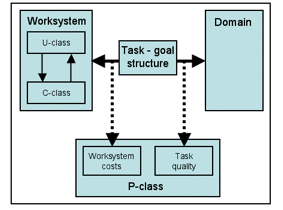
The conception of Engineering Design Principles (EDPs), proposed by Cummaford & Long [4], specifies the knowledge representations, sufficient to support development and validation of EDPs. This conception is shown in Figure 1.
Figure 1: EDP conception
Specifying criteria for identifying design problems, to which an EDP may be applied, ensures that the knowledge is applied only to those design problems for which it supports the specification of a design solution. Design problems contain not less than one or more users, interacting with not less than one or more computers, and some desired performance. The scope of the EDP thus comprises a class of users (U-class), a class of computers (C-class) and a class of achievable performances (P-class). If the user and computer in the design problem are members of U-class and C-class respectively, and the desired performance stated in the design problem is a member of P-class, then a design solution would be produced and the actual performance of the solution would equal the desired performance as stated in the design problem. The relationship between U-class, C-class and P-class is developed by empirical testing of the implemented design solutions, produced by EDP operationalisation. If the user, computer, or the desired performance, are outside the scope of the principle, then there is no guarantee that the design solution may be specified then implemented.
The EDP conception specifies relations between its representations, which can be validated. First, the user and computer models contain sufficient structures, to support behaviours, which carry out the task-goal structure (TGS), whilst incurring IWS costs. Second, the TGS achieves the product goal, for some Tq. The EDP conception thus relates statements of performance to the models, supporting operationalisation, and so, validation. EDPs comprise conceptualised, operationalised, tested and generalised design knowledge, which supports the diagnosis and prescription of a class of design solutions (CDS), which satisfies a class of design problems (CDP). Thus, the specification of design problems and design solutions, at the class level, is a pre-requisite, and so, necessary process of EDP development. To support the ultimate specification of EDPs, there is a need iteratively to identify CDPs and their CDSs, and extract both commonalities between them, and between the commonalities themselves. The latter constitute an EDP, which applies to all design problems within its scope.
In this paper, the process of CDP and CDS development is reported, to illustrate the application of an EDP development strategy. The result, comprising class representations of the user, computer, domain and TGS for the CDP and CDS, is exemplified (due to space limitations) with models from the first of two cycles of operationalisation. The process of EDP specification is then reported. The resulting initial EDP is exemplified again with reference to the first cycle of research.
2. Summary of EDP Conception
The conception proposed thus far comprises the following concepts and relationships.
For any design problem {user, computer, Pd} and any EDP {U-class, C-class, P-class, substantive component, methodological component}:
- If user is a member of U-class and computer is a member of C-class, then user structures and behaviours and computer structures and behaviours, as stated in the substantive component, are present.
- If user structures and behaviours and computer structures and behaviours as specified by the substantive component are present, then the task goal structure specified by the methodological component is achievable.
- If the task goal structure specified in the methodological component is effected by a worksystem comprising the structures and behaviours specified in the substantive component, then the product goal will be achieved, task quality will be x, user costs will be y and computer costs will be z.
- If task quality x, user costs y and computer costs z are achieved, then Pa = Pd.
- Therefore, Pd is a member of P-class for a worksystem comprising instances of U-class and C-class.
This conception may be said to be coherent, as it is based on two relationships: the relationship between the task goal structure and Tq for some product goal, and the relationship between the worksystem structures and behaviours, sufficient to achieve this task goal structure, and Uc and Cc. These relationships may be said to be coherent, as performance is a function of the effectiveness with which some task goal structures are achieved by some worksystem structures and behaviours. The EDP conception may be considered complete, as the concepts of the conception of the engineering discipline of HCI, which inform its development, appear within it. The issue of fitness-for-purpose will be addressed via operationalisation of the EDP conception to inform the development of EDPs, which may then be tested and generalised.
3. Validation and Ascription of Guarantees to EDPs
Operationalisation of the EDP conception as EDPs supports empirical testing of the class-level design solutions prescribed. This testing establishes whether the EDP conception is fit-for-purpose, that is, it supports the specification then implementation of a design solution, which achieves the desired level of performance as stated in the design problem. The fourth stage of validation, generalisation, involves establishing the generality of the EDP conception. These four stages of validation support the ascription of a guarantee that a worksystem, which performs the task goal structure, and specified in the methodological component of the EDP, achieves a level of Tq within the P-class, as stated in the EDP. A second guarantee, that the substantive component supports the specification of a worksystem which exhibits the structures and behaviours sufficient to achieve the task goal structure, as specified in the methodological component, whilst incurring a level of costs within the P-class, as stated in the EDP, may then be ascribed. A third guarantee, that correct application of the EDP to a design problem within its scope supports the specification then implementation of a design solution, which achieves Pd, is then ascribed on the basis of the former guarantees and further empirical testing. EDPs thus support the specification then implementation of a design solution, which achieves the desired performance if the design problem is within the scope of the EDP.
4. ‘Instance first’ and ‘class first’ strategies
Stork & Long [5, 6] have applied the Dowell & Long conception of HCI, to establish a basis for developing EDPs. They have operationalised the general HCI design problem by metricating the concepts, of which it is comprised, to express a specific design problem (SDP) in the domain of domestic energy management. Metrication provides observable and measurable criteria against which to assess performance. The design solutions (SDSs) of such specific design problems and the abstraction of prescriptive knowledge would constitute an EDP – the goal of Stork & Long. However, the operationalisation of an SDP does not, as such, ensure that a CDP, of which the SDP is an instance, will be found. This strategy may be termed the ‘instance first’ strategy, as it seeks to develop EDPs by specifying design knowledge for SDPs, by means of SDSs, and then generalising across instances. This approach may be contrasted with an alternative ‘class first’ strategy for EDP development, as proposed in this research [7].
5. Class development
The first phase of the ‘class first’ strategy for CDP development involves identification of an SDP and a corresponding SDS. The second stage involves identifying further SDPs, which require a similar Pd, which supports specification of P-class. The user(s) and computer(s), which are to achieve P-class are then assessed for similarities. They may be considered similar, if the user(s) and computer(s), specified in each SDP, comprise sufficient structures supporting sufficient behaviours to achieve P-class. If this sufficiency holds, these user(s) and computer(s) form U-class and C-class of the CDP respectively. In practice, once P-class has been specified, developing CDPs involves identifying U-class and testing instances (members) of this class interacting with instances of C-class. These instances of U-class and C-class are then used to inform the development of a CDS, which achieves P-class. No claims are made for the objective ‘reality’ of such classes, they are abstractions which are validated by their utility in supporting the definition of successful design solutions.
6. Identification of promising classes
A class may be considered promising for development if, for some SDP, a corresponding SDS exists and there are other SDPs, which share features of the solved SDP. Once such an initial class hypothesis has been formulated, the viability of the class may be assessed by examination of the work performed and the worksystem structures and behaviours sufficient to achieve Pd. If the performance achieved by the worksystem (Pa), specified in the SDS, is similar to the Pd of other SDPs (i.e. Pa = Pd), then the SDPs show promise for CDP development.
7. Costs matrix
The need for a systematic means of evaluating the SDP and SDS, and CDP and CDS systems in terms of their relative performance led to the development, in this research, of the ‘costs matrix’ [8, 9]. The costs matrix provides a systematic means of representing the relationship between the work, how well it is achieved by the worksystem, and the costs which are consequently incurred by the user. Specification of these relationships facilitates the comparison of competing solutions to a design problem in a systematic manner.
The costs matrix is constructed by listing the user abstract and physical behaviours on the y axis and tasks on the x axis. The cells of the matrix are instantiated by analysis of user data in the task goal structure. The cumulative abstract and physical costs are represented separately, as it is assumed that there is no equivalence in cost between an abstract and a physical behaviour. The costs matrix is also used to collate measurement of task quality, measured in terms of task completion rates, and time taken to complete each task.
The costs matrix supports comparison of competing design solutions to a design problem in terms of their relative performance. However, such comparisons are only valid if the elements on both axes are the same for each analysed design solution, and the means of evaluation is consistent between the systems analysed. The operationalisation of the costs matrix to measure the comparative performance of CDP and CDS systems is exemplified in the case study used to illustrate the stages of the method that follows.
8. CDP / CDS specification method
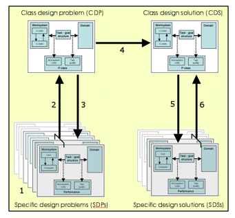
The following method for CDP and CDS specification was developed during this research [7] and operationalised during two cycles of research. The method stages are shown in Figure 2. CDP and CDS specification involves first specifying SDPs (1), by testing existing systems and identifying instances for which Pa ≠ Pd. The CDP is then specified, by abstracting commonalities from them (2). The resulting model is evaluated, by checking that the class user and computer models can be operationalised to complete the TGS for each SDP (3). Existing HCI design methods are applied to the CDP, to specify a CDS (4). To evaluate Pa of the CDS, it is decomposed into SDSs to enable testing by the target user group (5). Pa is abstracted from the SDSs’ performances (6). A complete CDP and CDS were specified for Cycle 1 and for Cycle 2 of this research, using this method. Each stage in the method is illustrated with a summary from Cycle 1 of the research.
Figure 2: CDP & CDS specification method
8.1: Specify SDPs
8.1.1 Requirement
First, a promising class of systems is identified on the basis of (informal) similarities in work performed. Second, examples of such systems are selected for testing. If these systems achieve a desired level of performance, they constitute specific design solutions (SDSs). If Pa ≠ Pd, they constitute specific design problems (SDPs). The SDP representations specify the domain objects, sufficient to characterise the work performed by the IWS, to achieve the product goal by operationalisation of the TGS. The IWS, comprising user and computer models, specifies the structures sufficient to support behaviours, to achieve the TGS. Performance, expressed as Tq and Uc and Cc, is established empirically.
8.1.2 Instantiation
Two e-shops were selected on the basis that they exhibited similarities in the type of work supported, namely the sale of homogeneous physical goods. Both e-shops informally appeared to have actual performances that did not equal desired performance, and so were considered promising for the specification of SDPs. The two e-shops selected were both live commercial operations at the time of the research.
Stash Tea (www.stashtea.com) is a US-based retailer offering a range of tea and tea-related products. Herbs of Grace (www.herbsofgrace.co.uk) is a UK-based retailer offering a range of herbal products, e.g. essential oils, natural herbs and herbal tablets. The e-shops achieved similar product goals, but exhibited different behaviours.
In order to ensure that the systems did not change during the course of the empirical testing, screenshots were taken and used to create prototypes (offline simulations) of each e-shop. The use of prototypes ensured that all participants interacted with the same e-shop design, and that the analytical data in the relevant Costs Matrix was also based on exactly the same system as the empirical data.
Six users, who had experience of online shopping, were recruited for testing. The testing required the users to attempt to complete a range of tasks. The latter ensured that relevant aspects of the transaction were evaluated, e.g. removing items from the order, as well as adding them. Actual Tq was lower than desired, as not all users completed the tasks. Uc were inferred from user behaviours[1] and verbal protocols, and enumerated in a Costs Matrix. The SDPs are not included here, due to space limitations, but differences between the SDPs and the CDP are reported later.
8.2: Specify CDP
8.2.1 Requirement
Following SDPs specification, commonalities are abstracted to construct the CDP. This abstraction comprises common aspects of the SDPs, to provide an initial CDP expression. The domain model is also abstracted, to express the product goal in terms of domain transformations. The TGS is then similarly abstracted. The IWS model is likewise abstracted from the SDPs. As class users are an abstraction, which cannot be tested directly, Pa for the CDP is derived from the SDPs tested.
8.2.2 Instantiation
Here, the CDP domain model was abstracted from the SDP domain models tested. The domain transformations to achieve the product goal were then specified. The TGS, to achieve the product goal was then specified, by abstraction from the SDP TGSs. The U-class and C-class, comprising the IWS, were then specified, to contain the minimal set of behaviours to enable the domain transformations to effect the TGS. Performance was then derived by calculating the mean performances of the SDPs tested.
8.2.2.1 Domain Model
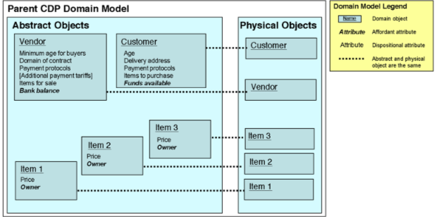
The domain model was the same for the two tested SDPs, and so was synthesised as the CDP. However, the reviewed e-shops sold different goods (e.g. herbal remedies, tea, etc.). The goods were therefore specified generally as ‘homogeneous physical goods, of which multiple units of multiple items are typically ordered’. This specification constrains instances of the CDP to transaction systems, which support collation of an order, containing multiple items, and which incur shipping (i.e. delivery) price, as part of the total transaction price.
Figure 3: CDP Domain Model
8.2.2.2 Product Goal
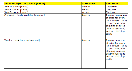
The affordant domain attributes (shown in bold in the domain model) are changed by the worksystem, in order to achieve the Product Goal. The dispositional domain attributes must have the values specified in the Product Goal, in order for it to be possible for the work to be done. The class domain model does not contain specific values for the object attribute values. The requirements for the object attribute values are specified in the Product Goal. The Product Goal (termed ‘CDP1-PG’) specifies the required values for the dispositional domain object attributes, and a specification of the affordant domain attribute value transformations that comprise the work.
Table 1: CDP1-PG: Dispositional Object Attribute value requirement
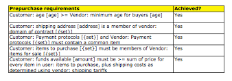 Table 2: CDP1-PG: Affordant Object Attribute value transformations
The relationship between domain transformations, and IWS behaviours to effect these transformations, is represented in the TGS.
8.2.2.3 Worksystem Models
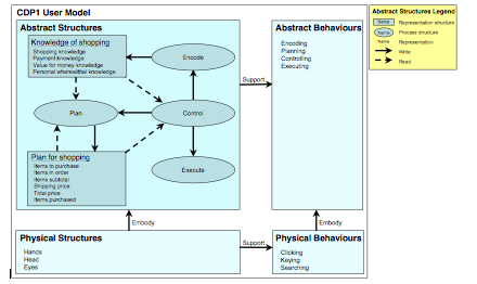
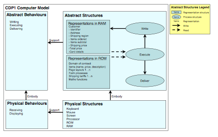
The class worksystem comprises a class user, termed ‘CDP1-U’ and shown in Figure 4, who interacts with a class computer, termed ‘CDP1-C’ and shown in Figure 5. CDP1-U and CDP1-C both comprise Representation Structures and Process Structures. Both CDP1-U and CDP1-C were abstracted from the commonalities between the respective specific user and computer models in SDP1a and SDP1b.
Figure 4: CDP1 User Model (CDP1-U)
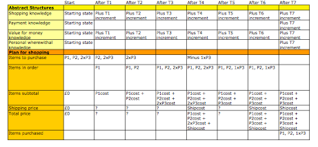
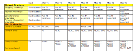
CDP1-U comprises two types of abstract structure. Representation structures (shown in boxes in the model) have particular states, e.g. ‘items ordered’, which are transformed by process structures (shown in ovals in the model, e.g. ‘Encode’). The representation structure states for each stage of the work are detailed in the representation structure states matrix. Process structure activation of representation states was assumed to support user abstract behaviours. The user abstract behaviours incurred during the work, are specified in the TGS, described later.
Table 3: CDP1-U Representation Structure States Matrix
The process structures in CDP1-U support abstract behaviours, which are defined as ‘planning’, ‘controlling’, ‘perceiving’ and ‘executing’. The abstract structures in CDP1-U are embodied by its physical structures, which also support physical behaviours, i.e. ‘clicking’, ‘keying’, and ‘searching’.
CDP1-C, like CDP1-U, comprises both representation structures and process structures, which support abstract behaviours. The abstract structures are embodied by physical structures, e.g. memory, processors, which support physical behaviours.
Figure 5: CDP1 Computer Model (CDP1-C)
8.2.2.4 Task-Goal Structure
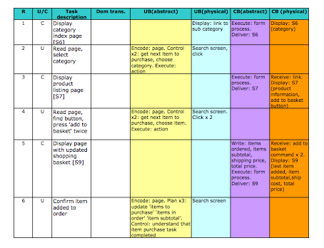
CDP1-U and CDP1-C interact to effect a number of task goals in order to achieve CDP-PG. The user and computer behaviours, which interacted to achieve the task goals, are specified in the class Task-Goal Structure (termed ‘CDP1-TGS’). An excerpt from CDP1-TGS is presented in Table 4. The total number of each behaviour required to complete the tasks in the TGS-class was derived by taking the mean value for each behaviour across SDP1a and SDP1b. These values are represented in the CDP1 Costs Matrix, specified in Table 5.
Table 4: CDP1-TGS: T3 ‘Order 2 units of item 3’
8.2.2.5 Performance
Performance is abstracted from testing the SDPs, instances of the CDP. Tq is expressed as the percentage of successful attempts to complete the product goal. IWS costs are expressed as the number of behaviours performed. Costs are measured, using the Costs Matrix. Cc are not reported here, due to space limitations.
8.2.2.5.1 Task quality
81% of tasks were successfully completed during SDP testing. Tq is less than desired, that is, 100%.
8.2.2.5.2 User costs
Uc are incurred, whilst learning to achieve the product goal (‘set-up costs’), or during execution of the TGS behaviours (‘runtime costs’). Acceptable setup costs are essentially zero, as target users are able to complete a transaction with no previous training (they are specified as having used the internet previously, and having experience of using credit-card-style payment technologies). Pd is for lower runtime Uc than the SDPs. An increase in Cc is considered acceptable, if this supports a reduction in Uc, or an increase in Tq (as required earlier).
Runtime costs were calculated using the Costs Matrix, one of which was constructed for each user interacting with each SDP. The matrix was completed by giving a score of 1 for every observed or inferred user behaviour. The mean values for users were then calculated (shown in Table 5). Costs support diagnosis of ineffectiveness in the SDPs, and enable comparison with potential design solutions. The tasks in Table 1 constitute the TGS to achieve the product goal. Similar tasks were used during evaluation of the CDS, to support direct comparison of performance. Tasks 1-3 involved ordering goods; Tasks 4 & 6 were ‘find total price’; Task 5 was ‘delete items’; and Task 7 was ‘complete transaction’.
Table 5: CDP1 Costs Matrix (CDP1-CM)
The CDP, here, comprises all the representations, specified in the EDP conception, and as such, is considered acceptable.
8.3: Evaluate CDP
8.3.1 Requirement
To ensure that the CDP is sufficient to characterise SDP behaviours, it is evaluated analytically, with respect to the TGS for each SDP. The IWS behaviours of the CDP are operationalised to achieve the TGS for each SDP. If the CDP IWS achieves the TGS, then the CDP is retained. If there are insufficient behaviours, then SDP / IWS differences must be re-synthesised. If they are too dissimilar to support synthesis, then a CDP cannot be abstracted.
8.3.2 Instantiation
The e-shops evaluated during the specification of SDP1a and SDP1b exhibited different behaviours at the device level of description, e.g. shipping prices required the user to find international shipping rates and calculate the likely shipping cost in SDP1a, whilst the user had to register to find shipping costs in SDP1b. These differences resulted in a similar product goal being achieved, but with different actual performances. However, aspects of the work resulting in high workload were similar. They were therefore included in the CDP. The CDP user model (CDP1-U) and domain model (CDP1-D) were operationalised analytically, to check that the TGS in each SDP could be achieved. CDP1-U contained sufficient behaviours to achieve the TGS in each of the SDPs tested. The CDP was therefore retained.
8.4: Specify CDS
8.4.1 Requirement
Existing HCI design knowledge and methods are used to specify the CDS. The design stage specifies a TGS, which is achievable by the IWS, whilst incurring acceptable IWS costs and attaining desired Tq. Whilst performance can only be established by testing SDSs instantiated from the CDS, analytic methods can be used to establish the likely performance of the CDS prior to testing.
8.4.2 Instantiation
Best practice craft knowledge and guidelines were recruited to develop CDS1 [10-15]. In addition, behaviours resulting in low task quality or high user costs were identified and re-engineered to increase potentially achievable performance. Substantive HCI design knowledge was also recruited in the design [17-29]. In particular, the TGS, required to effect the product goal, was informed by mercantile models [30, 31], which specify transactions as having distinct phases, described as Negotiation, Agreement and Exchange. The outcome of the redesign was a re-engineered TGS. An example for the task ‘order two units of item 3’ is shown in Table 6. During CDP testing, calculation of total price, during order collation, was found to be a high-cost behaviour. The CDS TGS differed from the CDP TGS, in that shipping options may be selected at any point in the interaction, hence supporting calculation of shipping costs by the computer, during the Negotiation Phase of the transaction.
Table 6: CDS1-TGS T3 ‘Order 2 units of item 3’
The CDP TGS required credit card details to be entered by the user, before the computer displayed the total price, including shipping. The CDP testing indicated that this interaction reduced Tq, as some users were unwilling to enter this information, prior to knowing the total price. The CDS TGS presents the total price throughout the Negotiation Phase, enabling the user to complete a transaction, based on the total price, including shipping price (and so to achieve Tq). IWS costs, incurred whilst effecting the TGS, and the Tq achieved, were measured by testing SDSs, instantiated from the CDS. This testing is described in the next stage of the process.
8.5: Specify SDSs
8.5.1 Requirement
To evaluate the CDS, it is necessary to re-express it as specific design solutions (SDSs). As class users are an abstraction, and so cannot be tested directly, SDSs must be designed to enable CDS testing. It is necessary to instantiate more than one SDS to abstract CDS commonalities in performance.
8.5.2 Instantiation
Here, to evaluate the CDS, it was instantiated as two SDSs, to enable testing with specific users. The two SDS computer models were similar to the SDP computer models, but featured controls to allow the shipping options to be selected at any point during the Negotiation Phase. Two SDS prototypes ensured class performance.
8.6: Evaluate CDS
8.6.1 Actual Performance
The task descriptions contained in CDS1-TGS were abstracted from the commonalities between the TGSs in SDS1a and SDS1b. CDS1-TGS is therefore computer independent, as the computer-specific aspects of the SDS TGSs were not common between SDS1a and SDS1b. The class actual performance is derived from the mean number of each behaviour contained in the TGSs for SDS1a and SDS1b. These mean values are represented in the CDS1 Costs Matrix (termed ‘CDS1-CM’).
The class actual task quality was derived from the actual task quality of SDS1a and SDS1b. Both user costs and task quality are expressed in CDS1-CM, as shown in Table 7.
Table 7: CDS1 Costs Matrix (CDS1-CM)
8.6.2 Comparison of Pa and Pd
Task Quality
All instances which satisfy the pre-purchase requirements should result in the product goal being achieved. Actual performance is 100% task completion, therefore for CDS1 Pa = Pd, and can be considered a design solution.
IWS costs
User costs are acceptable and lower than the class actual costs, derived during specification of CDP1. A comparison of the cost differences between CDP1 and CDS1 is shown in the comparison Costs Matrix shown in Table 8.
Negative values indicate a reduction in costs between the CDP and CDS. Where costs increased between CDP and CDS, they are shown in red. Task completion rates show the increase in task completion percentages, rather than reductions in tasks failures, in order to maintain a consistency with the labelling of the Costs Matrices.
Table 8: Comparison of CDP1 / CDS1 Costs Matrices
The design solution is implementable using existing technologies, and so can be considered a valid design solution.
The user ratings of workload and comparative workload supported the conclusion that less workload was required to complete the tasks with the SDS systems. The SDS systems, and therefore by extension the CDS, were therefore considered to be acceptable, as they fulfilled the requirement in the Product Goals for the CDS and SDSs that the systems should result in lower user costs during task completion.
The CDS was therefore considered acceptable and retained.
9. EDP specification method
The method for specification of EDPs involves identification of commonalities between a CDP and its CDS, to form the scope of the EDP. Those aspects of the CDS which are not included in the CDP-CDS commonalities, and the negation of those aspects of the CDP which are not included in the CDP-CDS commonalities, are then used to define the prescriptive component of the EDP. The EDP achievable performance is then defined as the actual performance achieved by the CDS.
An EDP comprises three components: a scope (i.e. supports diagnosis), a specification (i.e. supports prescription), and a class of achievable performances (i.e. supports validation, leading to guarantee). The EDP defines class design knowledge, recruited from class design solutions. The method for EDP construction is as follows.
9.1: Define EDP scope
9.1.1 Requirement
The EDP scope defines the boundary of applicability of the EDP. The scope comprises a class of users and a class of computers, which interact to achieve a specified class of domain transformations within a specified class of domains. The EDP scope is defined by generification of the commonalities between the CDP and CDS. Defining the scope in this way ensures that sufficient components are in the CDP to enable the CDS components to be operationalised.
An EDP is prescriptive class-level design knowledge, with a specified scope of application. The scope of the EDP enables comparison with the scope of other related EDPs, to determine their relative generality.
9.1.2 Instantiation
The respective Product Goals, Domain Models, and User Models were identical for both the CDP and CDS. These models were therefore recruited extant to the EDP Scope.
The CDP1 and CDS1 user representation states had some commonalities. These are shown in Table 9. The remaining user representation states were not common, and were therefore not recruited to the EDP scope.
Table 9: EDP1-U representation structure states matrix
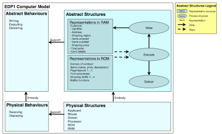
Not all CDP1-C and CDS1-C representation structures were common. In particular, the physical representation structures (i.e. screens and their components), and the abstract representation structures necessary to render these (i.e. page layouts and form processes) were not the same in CDP1-C and CDS1-C. These were therefore not recruited to the EDP scope. The commonalities between the computer models CDP1-C and CDS1-C were recruited to the EDP scope, and are represented in Figure 6.
Figure 6: EDP1 Computer Model (EDP1-C)
The CDP1 and CDS1 computer representation states had some commonalities. These are represented in Table 10. The remaining user representation states were not common, and were therefore not recruited to the EDP scope.
Table 10: EDP1 Scope: computer representation structure states matrix
The remaining components of CDP1 and CDS1 were not identical, and were therefore not recruited into the EDP1 scope. These non-identical components are presented in the next section.
9.2: Define Prescriptive design knowledge
The EDP prescriptive design knowledge is now synthesised from the non-common aspects of CDS1 and CDP1. The relevant components of CDS1 and CDP1 are first compared, in order to identify their non-commonalities. These non-commonalities are then used to construct the Prescriptive Component of EDP1. User and computer representation structure states are compared first, then user and computer behaviours. The computer physical structures, sufficient to support the user and computer behaviours identified, are also identified by reference to the user and computer behaviours.
9.2.1: Identify CDS-only and CDP-only components
The remaining components of the CDS comprise the aspects of the CDS which, if operationalised for the EDP scope components, will achieve the level of performance stated in the CDS. The CDS-only components are the crux of the EDP, offering a prescriptive specification of a TGS; user and computer representation structure states; supported user and computer behaviours (assumed to be commensurate with process structure activations); and achievable performance, as task quality and worksystem costs.
9.2.1.1 Identification of CDS-only and CDP-only abstract structures
9.2.1.1.2 User representation structure states
The CDS1 and CDP1 user representation structure states had some commonalities. These are represented in the EDP1 Scope. The remaining CDS1 and CDP1 user representation states were not common, and are therefore included here.
Table 11: CDS1 user representation states: non-commonalities
Table 12: CDP1 user representation states: non-commonalities
9.2.1.1.3 Computer representation structure states
The CDS1 and CDP1 computer representation states had some commonalities. These are represented in the EDP1 Scope. The remaining CDS1 and CDP1 computer representation states were not common, and are therefore included here.
Table 13: CDS1 computer representation states: non-commonalities
Table 14: CDP1 computer representation states: non-commonalities
9.2.1.1.4 Identification of CDS-only and CDP-only physical structures
The Computer physical structures, which supported the user behaviours specified in the TGS, are embodied in the screens, specified for CDS1 and CDP1. The CDS1 and CDP1 TGSs were each analysed by task. The computer physical structures, which supported the user behaviours in the TGS, were specified for each screen. The computer physical structures which were not also present in the CDP were then identified. These computer physical structures, which are present in the CDS, but not in the CDP, will be carried forward to the EDP prescriptive component later.
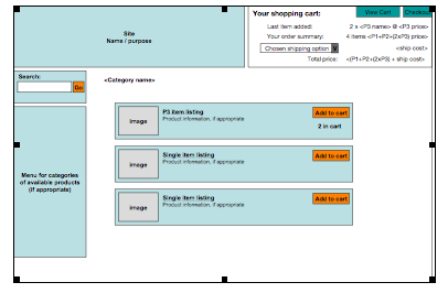
Space limitations preclude a full specification of the complete analysis here. The computer physical structures for Screen 9, referenced in Row 9 of CDS-TGS T3 (shown earlier in Table 6) are shown below, for illustration.
Figure 7: CDS1-C S9: 2x item 3 added
Required computer structures to support user behaviours (on the screen shown in Figure 7)
- Item quantity box
- Add to cart button
- Last item added
- Item subtotal
- Ship cost
- Total price
The method specified in stage 2A is now used to identify those aspects of the CDP, which are not represented in the CDP-CDS commonalities. Whilst the CDP-only components are not candidates for inclusion in the EDP, they may contribute to its specification by negation – i.e. if the CDP-only components are x, the EDP should specify not x. The CDP-only components are not exemplified here for reasons of space, but included computer structures such as a Recalculate button on the shopping cart page.
9.3: Synthesise EDP prescriptive component
The CDS-only and the negation of the CDP-only components are now synthesised to construct the EDP prescriptive component, comprising user and computer representation structure states, and supported user and computer behaviours.
9.3.1 User representation structure states
The user should be aware of the shipping cost and total price throughout their interaction with the e-shop. The user representation structure states will then be identical to those shown in Table 11.
9.3.2 Computer representation structure states
The computer should elicit sufficient information to enable the total price to be known throughout the transaction, i.e. sufficient information to calculate the shipping costs. The prescribed computer representation structure states are identical to those shown earlier in Table 13.
9.3.3 Computer physical structures
9.3.3.1 CDS-only components
The CDS screens are sufficient to support the behaviours in the CDS TGS. The CDS1 computer structures, which were not present in the CDP1 computer structures, are listed below, grouped by CDS1 screen. These non-commonalities are therefore necessary components of the EDP computer structures: screens.
Screen 2
- Last item added to cart
- Goods subtotal
- Shipping option selector
Screen 3
- Ship cost
- Total price
Screen 5
- Last item added
- Item subtotal
- Ship cost
- Total price
Screen 7
- Add to cart button
Screen 8
- Last item added
- Item subtotal
- Ship cost
- Total price
Screen 9
- Item quantity box
- Add to cart button
- Last item added
- Item subtotal
- Ship cost
- Total price
Screen 10
- Up and down arrows to change quantity
Screen 11
- Ship cost
- Total price
Screen 13
- Total price
Screen 15
- Items in order
- Total price
9.3.3.2 CDP-only components
The following structures were present in the CDP1 computer structures, but not in the CDS1 computer structures.
Screen 3
- Change quantity textbox
- Recalculate button
Screen 7.1a
- Shipping times and prices link
Screen 8.2a
- International shipping rates link
Screen 8.3a
- International shipping tariffs
The structures present in Screen 3 were not required in the CDS screens, as the item quantities in the shopping basket screen were updated through the use of the up and down arrow buttons.
The shipping times and prices information, and the links to this information, were not required in the CDS screens, as the shipping costs were calculated and displayed by the computer throughout the transaction.
9.3.4 Screens
The CDS1 screens are recruited to form the EDP1 screens. The CDS1-only non-commonalities identified earlier are the necessary components to support the EDP1-TGS, and the EDP1 screens are sufficient to achieve performance Pa = Pd.
9.3.5 Task-Goal Structure
CDS1-TGS is recruited to form the EDP-TGS. The TGS is not shown here, due to space limitations.
9.4: Define EDP achievable performance
The CDS actual performance, as task quality and worksystem costs, is recruited from the CDS to form the EDP class of achievable performances. The EDP1 achievable performance is thus shown in Table 7, the CDS Costs Matrix.
The EDP is thus defined. The method reported and exemplified here was operationalised for the CDPs and CDSs specified during Cycle 1 and Cycle 2 of the research to define initial EDPs.
10. Strategy assessment
The operationalisation of the ‘initial class’ strategy resulted in the specification of initial EDPs, and so offers promise for the eventual development of EDPs, supported by performance guarantees. This operationalisation indicates that the specification of class design problems and solutions is possible, and, as such, the ‘class first’ strategy was successful in this instance.
A number of specific issues were identified during the research, which should be addressed during future research. The specific issues are ordered, following the process stages of the method specified earlier.
10.1 Specify SDPs
10.1.1 Selection of systems for SDP development
The number of systems tested, to inform development of each CDP, was somewhat limited (i.e. two). Testing more systems would give greater confidence in abstracted similarities between instances. However, the work described here is intended to demonstrate the possibility of specifying CDPs and their CDSs, as an initial operationalisation of the ‘initial class’ strategy of EDP development. Once the process of developing CDPs and their CDSs has been shown to be feasible, such additional development efforts may then be justified.
10.1.2 Task selection
The tasks selected for inclusion in the TGS included a range of typical shopping activities. The tasks are sufficient to characterise any transaction performed on e-commerce sites, although the number of times each task is completed will vary for each transaction. It was, however, considered desirable to standardise the tasks here in order to support systematic comparison of the SDP systems, both with respect to each other and to the SDS prototypes. Varying sub-task frequency, however, should be considered in future work.
For the domain of e-commerce transactions, the selection of goods, receiving of the collated order (for physical goods transaction systems) and payment are necessary tasks to enable completion of a transaction. In practice, the product goals for each SDP/S were defined in order to ensure that completion of the tasks was necessary in order to achieve the relevant product goal. Future research should address the process of task selection based on the frequency and occurrence of tasks completed using any extant systems available. Other domains, e.g. Air Traffic Management, will have a commonly agreed corpus of tasks to be supported by the system, and development of EDPs for such domains would avoid these issues of completeness, with regard to task selection.
10.1.3 SDP prototypes
Whilst actual payment was simulated in the testing, users reported that they would be uncomfortable entering their own payment authorisation before knowing the total price payable. Tq was thus based on a simulation, with its inevitable differences with actual transactions, and so might be questioned. However, such ineffectiveness has also been shown to occur for e-shops generally [27].
Simulation of system functionality during the empirical testing was considered to have been successful, in that the results agreed with the users’ subjective ratings of workload incurred using the SDP and SDS systems. However, it would have been preferable to have used functioning e-shops, instead of simulating computer functionality, in order to measure time-to-complete for each task more systematically, and at a finer level of granularity. The decision to use prototypes with system behaviours simulated by the researcher was taken in order to allow the project to be completed within the practical constraints of the research project. In future research, functioning prototypes should be employed if possible, to enable more consistent and finer-grained analysis of task completion times.
10.1.4 Model selection, development and specification
The user, computer and domain models were based on previous work by Hill et al [32, 33]. The choice of user model and model format was based on the premise that Hill et al’s models were based on the Dowell & Long conception, and so contained the appropriate elements necessary to operationalise the conception during the research. The operationalisation of an alternative format for the worksystem and domain models would be possible within the existing methods specified within the research. It would be interesting to consider alternative choices of user, computer and domain models in future research.
The process of model development was similar for each SDP, and is now summarised, to inform future research. The domain transformations required to achieve the product goal were specified first, in order to inform development of the domain model. This ensured that the domain model contained only those objects whose attribute values were transformed during the work. The TGS was then specified in two stages. In the first stage, the user and computer behaviours sufficient to achieve the domain transformations specified in the product goal were identified. In the second stage, the user and computer structures, sufficient to support the behaviours identified in stage one, were specified. The user and computer models were then specified, by identification of the minimal set of user and computer structures, sufficient to support the behaviours identified in the TGS.
The first iteration of model development did not include user and computer structures in the TGS. However, the lack of user and computer structures in the TGS obviated the explicit relation of the TGS to the user and computer models, and so user and computer structures were then included in the TGS. The requirement for coherence between the models required repeated iteration of the models, as insights identified during development of the user and computer models were used to reverse engineer the TGS, domain model and product goal.
User behaviours were assumed to be equivalent in terms of workload (Uc). Whilst these behaviours undoubtedly involve user workload, the relative workload of each may well not be equal. Empirical evidence for differential workload between behaviours could be integrated into the Costs Matrix. Physical costs were enumerated by counting directly observable user behaviours, but abstract costs were inferred from tasks performed by the user, and from verbal protocols. A standardised set of encoding criteria informed identification of user abstract costs, which assumed the cost of encoding each page of information to be equivalent to the cost of mental (structure) activation. The criteria, and the equivalence of costs incurred during behaviours and activation of associated structures, could usefully be explored further in future work.
10.2 Specify CDP
Pd for the CDP was specified relative to the Pa of the SDSs tested (i.e. increase Tq, reduce Uc). Whilst it is possible, in principle, to state Pd as absolute values, such absolute values were not employed here. Future EDP development should support address of this issue.
User abstract and physical behaviour counts were not included in the CDP TGS tables, even when the CDP TGS contained a table taken directly from the SDP TGS and otherwise unaltered. The decision to remove the behaviour counts was taken because the CDP Costs Matrix contained the mean count for each user behaviour, for all SDPs included in the CDP.
10.3 Evaluate CDP
Analytic evaluation of the CDP involved checking that sufficient structures and behaviours were present in the user and computer models, to perform the TGS of each SDP. This assessment supported evaluation of the CDP user and computer models. This process was considered necessary, in order the better to inform the development of the subsequent EDP.
10.4 Specify CDS
User abstract and physical behaviour counts were not included in the CDS TGS, even though they were generally consistent between SDSs. Whilst the counts were similar for the CDSs developed here, it was anticipated that this might not necessarily be the case for all CDS systems, and so the counts were calculated using the mean values across SDSs, to enable the CDS TGS to operate at greater levels of generality in future design instances.
Specification of the CDS TGS involved re-engineering of the CDP TGS to reduce Uc, whilst maintaining Tq. The empirical testing carried out at this stage enabled the results of the re-engineering process to be evaluated, in terms of Tq. This approach offers some promise for the improvement of current HCI design practices, and will be investigated further in future by the researcher.
The specification of discrete user mental structures was based on the user mental behaviours identified during analysis of each task. The process by which behaviours are identified as being instances of separate behaviour types (e.g. calculate, read, etc) is therefore an important factor impacting the final enumeration of user costs, and the contents of the user model. The identification of behaviour types, and the subsequent identification of user mental structures should be investigated further in future research.
10.5 Specify SDSs
The SDS prototypes exhibited features, which were ported from the SDP systems tested. Such inclusions ensured that differences in performance between the SDPs and SDSs were due to differences in the CDP and CDS, rather than to specific features of the e-shops and SDS prototypes.
The features ported from the SDP to the SDS are therefore not present in the initial EDP. The initial EDPs could not, therefore, support specification of a novel SDS for which no SDP system exists. This issue of completeness must be investigated further during future applications of the initial EDPs, in order to identify those features which should be included in the EDP, such that the EDP will support specification of a SDS for which no SDP system exists.
10.6 Evaluate CDS
Structures were specified for both the user and computer models. However, workload was calculated without reference to structures, suggesting that structures are not a necessary component of the models for the purpose of measuring workload. However, structures offer a more complete characterisation of the worksystem, and would be necessary to characterise costs that are incurred when CDP and CDS structures change (that is, when structure ‘set-up’ costs are not zero).
10.6.1 Mapping the CDS to CDP
Whilst the CDP and CDS cannot be tested directly, the differences in performances of their instantiations indicate that the CDS achieved more effective performance than the CDP. Subjective reports of workload (Likert scales of task difficulty completed by users after testing) indicated that the SDS prototypes incurred less costs in general (as perceived by users) than the SDP systems. These subjective ratings of relative workload agreed with the relative costs calculated using the costs matrices, so offering informal support for the validity of the analytically derived calculations of relative workload.
10.7 EDP definition method
Two initial EDPs were specified using the method specified earlier, and so the method appears to offer promise for the development of further initial EDPs in future. The method identified the computer structures necessary to support the user and computer behaviours, specified in the CDS TGS, and so offers promise for the validation of this relationship in future research.
10.8 Initial EDPs
The initial EDPs offer promise for the specification of a ‘parent’ EDP via abstraction. However, this was not achieved during the timescale of this research. The informal similarities, which indicate what might be specified in an initial EDP at the parent-class level, are twofold:
First, the price of items should be clearly displayed throughout the transaction. Second, the total price payable should be made available to the user as early as possible in the transaction, and any user costs incurred in providing the minimal data required to specify the total price are to be considered acceptable (e.g. the user costs involved in entering the shipping option in CDS1 would be acceptable, as the shipping option data enabled the total price to be known earlier).
The specification of an initial EDP at the parent-class level would enable its application to solve design problems, which are instances of the parent class, but not of either of the two subclasses identified in this research. Such application would support better specification of the scope of each of the classes. The identification of design knowledge at an appropriate level of generality is a key aspect for the development of performance guarantees and, as such, is an important aim for future research in this area.
The next phase of research should address application of the EDPs, to novel SDPs within the scope of each EDP. This is likely to inform the expression of the EDPs, and will offer further insights into the appropriate level of class generality.
10.9 Review of requirement for validation, leading to guarantee
The research has specified HCI design knowledge at the class level, so offering promise for validation of the design knowledge, leading to guarantee, due to the completeness of the design solution specification. The design solutions were characterised in terms of their domain transformations, enabling relations between the work, the worksystem and performance to be specified explicitly. The use of Dowell & Long’s conception of HCI was therefore considered to be an appropriate decision, as the explicit and separate specification of the domain model offers promise for validation, leading to performance guarantees, in future research.
The method for ascribing guarantees of application, described earlier, involves empirical testing in order to develop and ascribe guarantees. It may be considered feasible to ascribe guarantees when testing carried out by multiple researchers, on multiple SDSs developed via application of the EDPs, yields consistent results. However, given the nature of empirical validation, the validity of the EDP can only be shown to be resistant to falsification, and cannot lead, a priori, to a definitive statement of guarantee.
10.10 EDP applicability, and their potential as design support
EDPs are a long-term goal of this research, and the form of their expression remains an issue to be addressed. However, the research has delivered interim products, in the form of initial EDPs. The EDPs comprised both necessary features of CDSs (i.e. the CDS-only computer structures identified) and a complete set of computer structures and behaviours, sufficient to specify a complete SDS. As such, the initial EDPs may be applied to novel SDPs which are within the scope of the respective EDP. Whilst the initial EDPs therefore exhibit utility and fitness for purpose, their expression needs to be developed further in future research.
The engineering of user behaviours at the class level was an effective design technique, and is lacking in current best practice design techniques. However, the current method of costs diagnosis requires further research in order to be feasible in practice.
11. Future research discussion
The EDPs were defined, but need to be applied and tested, to enable validation. Application of the initial EDPs will allow the format of their expression to be evaluated, and it is likely that this process will inform further development of their expression.
Application of the user model to diagnose user costs was work-intensive, and is currently not sufficiently well-specified to support multiple practitioners in achieving consistent results. The user model, and procedures for diagnosis user costs, may be considered fit-for-purpose when multiple analysts achieve consistent results, when analysing the same SDP. In order to achieve this goal of analyses delivering consistent results, the criteria for the diagnosis of mental behaviours should be further investigated. It may be that an alternative user model would also be required, to support a more consistent set of criteria for diagnosing mental costs.
The potential savings in development costs offered by the availability of EDPs as design support are significant. The development costs involved in EDP definition, whilst significant, are less than the potential benefits, assuming even modest take-up of the EDPs by commercial practitioners.
The current research has focused on developing the methods necessary for EDP specification, and operationalisation of these methods to specify initial EDPs. It is interesting to note that, once validated EDPs have been developed, the specification of EDPs and their application will not be carried out by the same analysts. The EDPs must therefore contain sufficient components to support specification of SDSs. In the research reported here, elements of the SDS may have been informed tacitly by design knowledge held by the researcher, which was not specified explicitly in the initial EDPs.
The research reported here involved identification of a parent class of e-commerce transaction systems, which contains two subclasses. Future research should investigate the feasibility of further subclasses of this parent class, in order to better understand the specification of design knowledge at varying levels of generality. In addition, the boundary conditions of the two subclasses should be investigated. Whilst the subclass of physical goods transaction systems, identified in Cycle 1 of this research, may well include a great number of SDPs, the class criteria should be reviewed in light of SDPs which are similar in some respects, but may be solvable using an alternative CDS. For example, SDPs for online (grocery) supermarkets are within the scope of the class of physical goods transaction systems, and as such, SDSs could be specified for these systems using the initial EDP, but an alternative EDP, supporting the design of SDSs with superior performance, could be specified.
The EDP conception and definition methods should also be operationalised for other classes of design problem, in order to investigate the generality of the methods across multiple classes of design problem. Operationalisation of the EDP definition methods would also allow the format of EDP expression to be refined. Once such work has been undertaken, it will be possible to gain further insights into the definition of EDPs at varying levels of generality, in a number of distinct domains.
References
1: Dowell, J. & Long, J. B. (1989) Towards a conception for an engineering discipline of human factors. Ergonomics 32, pp. 1513-1536
2: Sutcliffe, A. (2000) On the effective use and reuse of HCI knowledge. ACM Trans. Comput.-Hum. Interact. 7, 2 (Jun. 2000), pp. 197-221.
3: Long, J. B. (1996) Specifying relations between research and the design of human-computer interactions, International Journal of Human-Computer Studies, v.44 n.6, p.875-920, June 1996
4: Cummaford, S. & Long, J. B. (1998) Towards a conception of HCI engineering design principles, in T. R. G. Green, L. Bannon, C. P. Warren & J. Buckley (Eds.) Proceedings of ECCE-9, the Ninth European Conference on Cognitive Ergonomics. EACE, pp. 79-84.
5: Stork, A. & Long, J. B. (1994) A specific planning and control design problem in the home: rationale and a case study. In Proceedings of the International Working Conference on Home-Oriented Informatics, Telematics and Automation. University of Copenhagen, Denmark, pp. 419-428.
6: Stork, A. (1999) Towards Engineering Principles for human-Computer Interaction (Domestic Energy Planning and Control). Unpublished Doctoral Thesis, University College London.
7: Cummaford, S. & Long, J. B. (2002) Solving class design problems: towards developing engineering design principles, in S. Bagnara, S. Pozzi, A. Rizzo & P. Wright (Eds.) Proceedings for ECCE-11 the Eleventh European Conference on Cognitive Ergonomics. EACE, pp.167-174.
8: Cummaford, S. & Long, J. B. (1999) Costs Matrix: systematic comparison of competing design solutions, in S. Brewster, A. Cawsey & G. Cockton (Eds.), Proceedings of Human-Computer Interaction INTERACT ’99 Volume 2, IOS Press, pp.25-26.
9: Cummaford, S. (2000) Validating effective design knowledge for re-use: HCI engineering design principles. In CHI ’00 Extended Abstracts on Human Factors in Computing Systems. ACM Press, New York, NY, pp. 71-72.
10: Brighton Usability Group (2003) The Brighton Usability Patterns Collection. Retrieved on 12 March, 2007 from http://www.cmis.brighton.ac.uk/research/patterns/home.html
11: Brown, C. M. (1999) Human-computer interaction design guidelines. Intellect, Exeter, UK.
12: Fincher, S. (2000) The pattern gallery. Retrieved on 12 March, 2007 from http://www.cs.ukc.ac.uk/people/staff/saf/patterns/gallery.html
13: Lim, K. Y & Long, J. B. (1994) The Muse Method for Usability Engineering. Cambridge University Press, Cambridge, UK
14: Smith, S. L., & Mosier, J. N. (1986) Guidelines for designing user interface software. Mitre Corporation Report MTR9240, Mitre Corporation. Retrieved on 12 March, 2007 from http://hcibib.org/sam
15: Thimbleby, H. (1990) User interface design. New York: ACM Press.
16: van Duyne, D. K., Landay, J. A., & Hong, J. I. (2003) The design of sites. Addison-Wesley, Boston, MA.
17: Bernard, M & Sheshadri, A. (2004) Preliminary examination of global expectations of users’ mental models for e-commerce web layouts. In Usability News 6.2, 2004. Retrieved on 12 March, 2007 from http://psychology.wichita.edu/surl/usabilitynews/62/web_object_international.htm
18: Bernard, M. (2002) Examining user expectations for the location of common e-commerce web objects. In Usability News 4.1, 2002. Retrieved on 12 March, 2007 from http://psychology.wichita.edu/surl/usabilitynews/41/web_object-ecom.htm
19: Bidigare, S. (2000) Information architecture of the shopping cart. Argus Centre for Information Architecture white paper. Retrieved on 12 March, 2007 from http://argus-acia.com/white_papers/shopping_cart_ia.html
20: Chaparro, B. (2001) Top ten mistakes of shopping cart design. In Internetworking 4.1, December 2001. Retrieved on 12 March, 2007 from http://internettg.org/newsletter/dec01/article_chaparro.html
21: Ketchpel, S., Garcia-Molina, H., & Paepcke, A. (1997) Shopping models: A flexible architecture for information commerce. In Proceedings of DL97, Philadelphia PA, USA.
22: Kienan, T. (2001) Boosting transaction usability. Retrieved on 12 March, 2007 from http://www.tauberkienan.com/ecommerce/transactionsystems.html
23: Poong, Y., Zaman, K., & Talha, M. (2006) E-commerce today and tomorrow: a truly generalized and active framework for the definition of electronic commerce. In Proceedings of the 8th international Conference on Electronic Commerce: the New E-Commerce: innovations For Conquering Current Barriers, Obstacles and Limitations To Conducting Successful Business on the internet ICEC ’06, vol. 156. ACM Press, New York, NY, pp. 553-557.
24: Silverman, B. (2001) Implications of buyer decision theory for design of e-commerce websites, International Journal of Human-Computer Studies, v.55 p.815-844.
25: Snow Valley (2005a) IMRG e-Retail standardisation report. Part 1: Transactional navigational elements style & terminology. Retrieved on 12 March, 2007 from http://www.snowvalley.com
26: Snow Valley (2005b) IMRG e-Retail standardisation report. Part 2: The checkout process. Retrieved on 12 March, 2007 from http://www.snowvalley.com
27: Spool, J. (2002). The customer sieve. User Interface Engineering
Retrieved on 12 March, 2007 from
http://world.std.com/~uieweb/Articles/customer_sieve.htm
28: User Interface Engineering (2001) Are the product lists on your site reducing sales? E-commerce white paper Retrieved on 12 March, 2007 from http://www.uie.com/publications/whitepapers/pogosticking.pdf
29: Walsh, I. (2003) Good information architecture increases online sales. Sitepoint 23rd October 2003. Retrieved on 12 March, 2007 from http://www.sitepoint.com/article/increases-online-sales
30: Hallam-Baker, P. (1996) User interface requirements for sale of goods. World Wide Web Consortium technical paper (draft). Retrieved on 12 March, 2007 from http://www.w3.org/ECommerce/interface.html
31: Kalakota, R. & Whinston, A. B. (1996) Frontiers of Electronic Commerce. Addison Wesley Longman Publishing Co., Inc.
32: Hill, B., Long, J. B., Smith, W., & Whitefield, A. (1993) Planning for multiple task work: an analysis of a medical reception worksystem. In Proceedings of the SIGCHI Conference on Human Factors in Computing Systems, CHI ’93. ACM Press, New York, NY, pp. 314-320.
33: Hill, B., Long, J. B., Smith, M. W. & Whitefield, A. D. (1995) A model of medical reception – the planning and control of multiple task work. Applied Cognitive Psychology. Vol 9, 81-114.
[1] Although the research specified the structures, supporting behaviours, as required by the HCIe conception (see earlier), only behaviours are reported here, due to space limitations.
